12 Aug
Welcome to the 2020.1 version of getting started with computer vision on Vitis on Zynq. The release of 2020.1 saw significant changes from the old 2019.2 version and we thought it would be useful to update this tutorial to reflect the newer version. We will even be covering two different methods: a quick start way and a more scripted build approach. This tutorial will be a multi-part series covering the basics of getting started with computer vision and Vitis. We will be covering:
- The quick start method (Current)
- The scripted build method using Petalinux and XRT
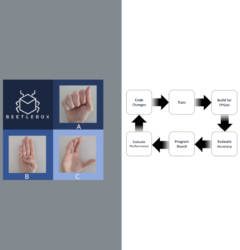
- How to build “Hello World” and understanding Vitis Development Flow
- Using OpenCV on the embedded system
We hope these tutorials will be useful for anyone looking to get into computer vision on FPGAs.
Part 1: The Quick Start Method
Using the pre-made image
To get easily started on Vitis 2020.1, Xilinx has provided all the necessary files to create a project and get running on our board. We will be looking at downloading, installing and extracting these tools
Pre-requisites:
- A version of Linux officially supported by Vitis
- A development board officially supported by Vitis (packages for officially supported boards can be found here)
- Vitis 2020.1 (Installation instructions can be found here)
- XRT (Installation instructions can be found here)
- Download the ZCU104 embedded base platform
- Download the ZYNQMP common image
- A SD card
- Balena Etcher or equivalent software
Our particular setup:
- Operating System: Ubuntu 18.04.04
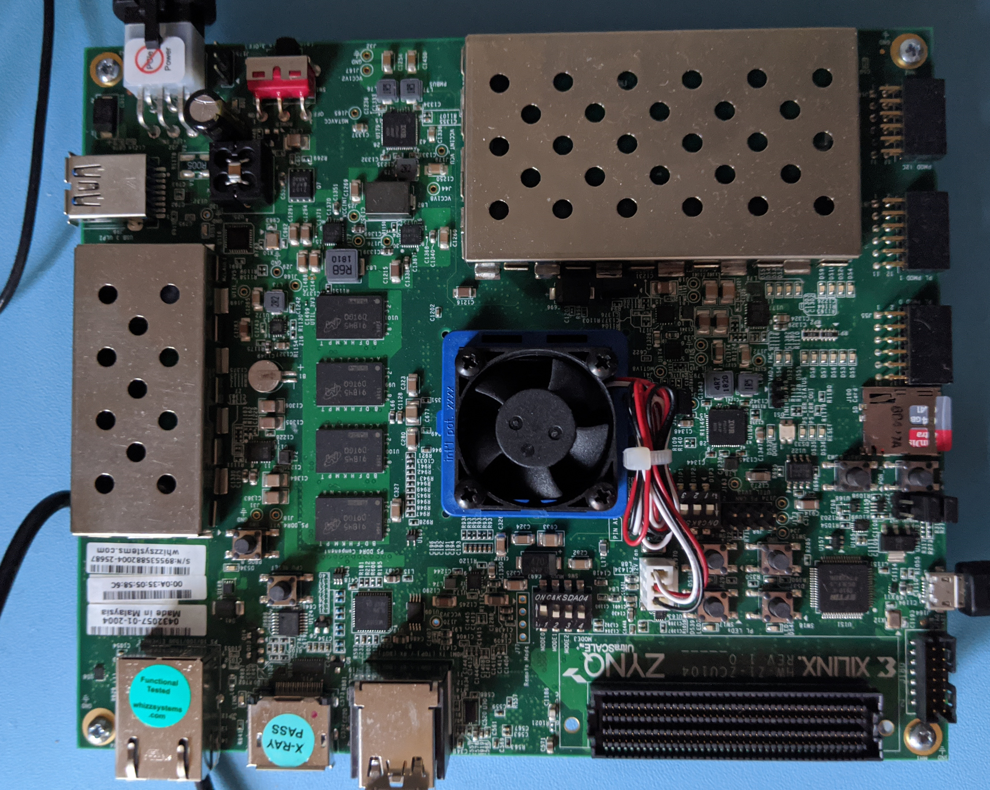
- Development board tested: ZCU104
Extracting our files
Our embedded base platform should be in a file called something similar to:
xilinx_zcu104_base_202010_1.zip
Extract the platform to the following directory:
<Vitis_install_path>/Vitis/2020.1/platforms
We also need to extract the files for our common image:
xilinx-zynqmp-common-v2020.1.tar.gz
It does not matter where this is extracted to, so we can keep it in the same directory where we downloaded it. We also need to create the sysroot, which we can do by running:
./<zynqmp_common_image_path>/xilinx-zynqmp-common-v2020.1/sdk.sh
which should display the following:
PetaLinux SDK installer version 2020.1
======================================
Enter target directory for SDK (default: /opt/petalinux/2020.1):
It does not matter where we extract to, so we can just keep it as the default:
You are about to install the SDK to "/opt/petalinux/2020.1". Proceed [Y/n]? Y
Extracting SDK..........................................................................................................................................................................done
Setting it up...done
SDK has been successfully set up and is ready to be used.
This has created our sysroot file system. We also need to extract our root file system which is held in the following folder:
./<zynqmp_common_image_path>/xilinx-zynqmp-common-v2020.1/rootfs.ext4.gz
We should now have all the files we need to create an application project in Vitis.
Create an Application project in Vitis
We need to setup our environment, which we can do through a new terminal:
source <Vitis_install_path>/Vitis/2020.1/settings64.sh
source /opt/xilinx/xrt/setup.sh
We can then run Vitis:
Vitis
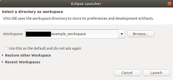
Launch with a new workspace:
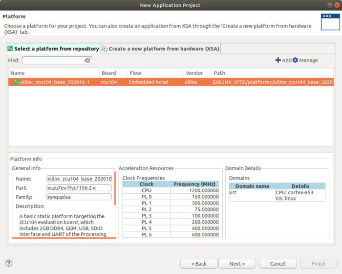
In the welcome tab of the Vitis IDE, click “Create Application project” and then hit next in the first panel. This will lead to the platform panel, where we can add our platform in the “Select a platform from repository” tab. Hit “Add” and then select the platform we just extracted:
<Vitis_install_path>/Vitis/2020.1/platforms/xilinx_zcu104_base_202010_1
Our panel should then look like this:
Hit “next” to go to the Application Project details panel. Here we just need to provide a name for our application project, for instance: vector_example. Hitting “next” will then take us to the domain panel:
- Under “Sysroot path” select:
<sdk_installation_directory>/sysroots/aarch64-xilinx-linux
- Under “Root FS” select:
<zynqmp_common_image_path>xilinx-zynqmp-common-v2020.1/rootfs.ext4
- Under “Kernel Image” select:
<zynqmp_common_image_path>xilinx-zynqmp-common-v2020.1/image
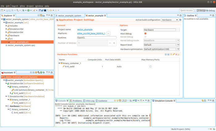
Click “next” to go to the Templates panel. Here we will select the “SW Acceleration Templates” and then “Vector Addition.” Then hit “finish,” which should take us to the Vitis IDE proper.
Testing our application project
To make sure everything is set up properly, we will quickly test that the Vector Addition example will run on our board. Under the “vector_example.prj” tab, change “Active Build Configuration” to “Hardware.” Then click the build icon (the little hammer) as shown:
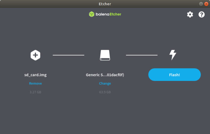
When Vitis has finished compiling, it creates a .img file that we are going to flash to our SD card. It is held in the following directory:
<path_to_workspace>/example_workspace/vector_example/Hardware/package/sd_card.img
This file contains everything the FPGA needs to run our application. Launch balena etcher and select the “sd_card.img” file and then select the SD card, you wish to write to:
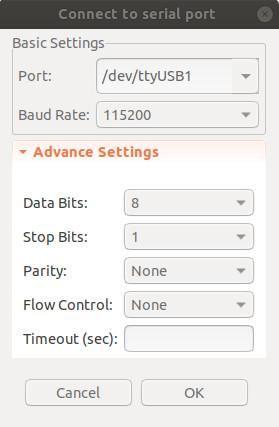
Once your SD card is flashed, check that the Zynq board is in “Boot from SD card mode” and that it the board is connected to the host via USB. In the Vitis IDE select “Window” > “Show View”, then search terminal and hit “Vitis Serial Terminal.” In the “Vitis Serial Terminal” hit the add button to launch the “Connect to serial port.” Keep the default settings the same apart from the ort, which will differ depending on the particular host computer:
Using the Vitis Serial Terminal, we can now run our program as follows:
cd /mnt/sd-mmcblk0p1/
source ./init.sh
./vector_example binary_container_1.xclbin
We should see the example successfully pass:
 212.148772] [drm] Pid 747 opened device
...
TEST PASSED
[ 213.258741] [drm] <- Hold xclbin A219526F-EE10-4F2E-8921-A60AD1B268FE, to ref=1
[ 213.271917] [drm] -> Release xclbin A219526F-EE10-4F2E-8921-A60AD1B268FE, from ref=1
[ 213.280203] [drm] now xclbin can be changed
[ 213.287942] [drm] <- Release xclbin A219526F-EE10-4F2E-8921-A60AD1B268FE, to ref=0
[ 213.303865] [drm] Pid 747 closed device
We have now successfully downloaded, installed and used a pre-made image to run a basic vector addition on Vitis 2020.1 Next time we will look at using scripts instead, which gives more control and a more automated workflow.